The first thing a machinist asks when making a part is, “how do I hold it?” A lot of times a vise or collet chuck is a good answer. There are a lot of techniques. For holding a flat part, often a good answer is to bolt the part to the table or a surface plate. There are a variety of ways to hold a part down, of course. This is an example of one method for holding a flat part for CNC machining. The technique here is more in using my CAM system to make tabs to retain a fully contoured part.
FLAT STOCK BOLTED DOWN
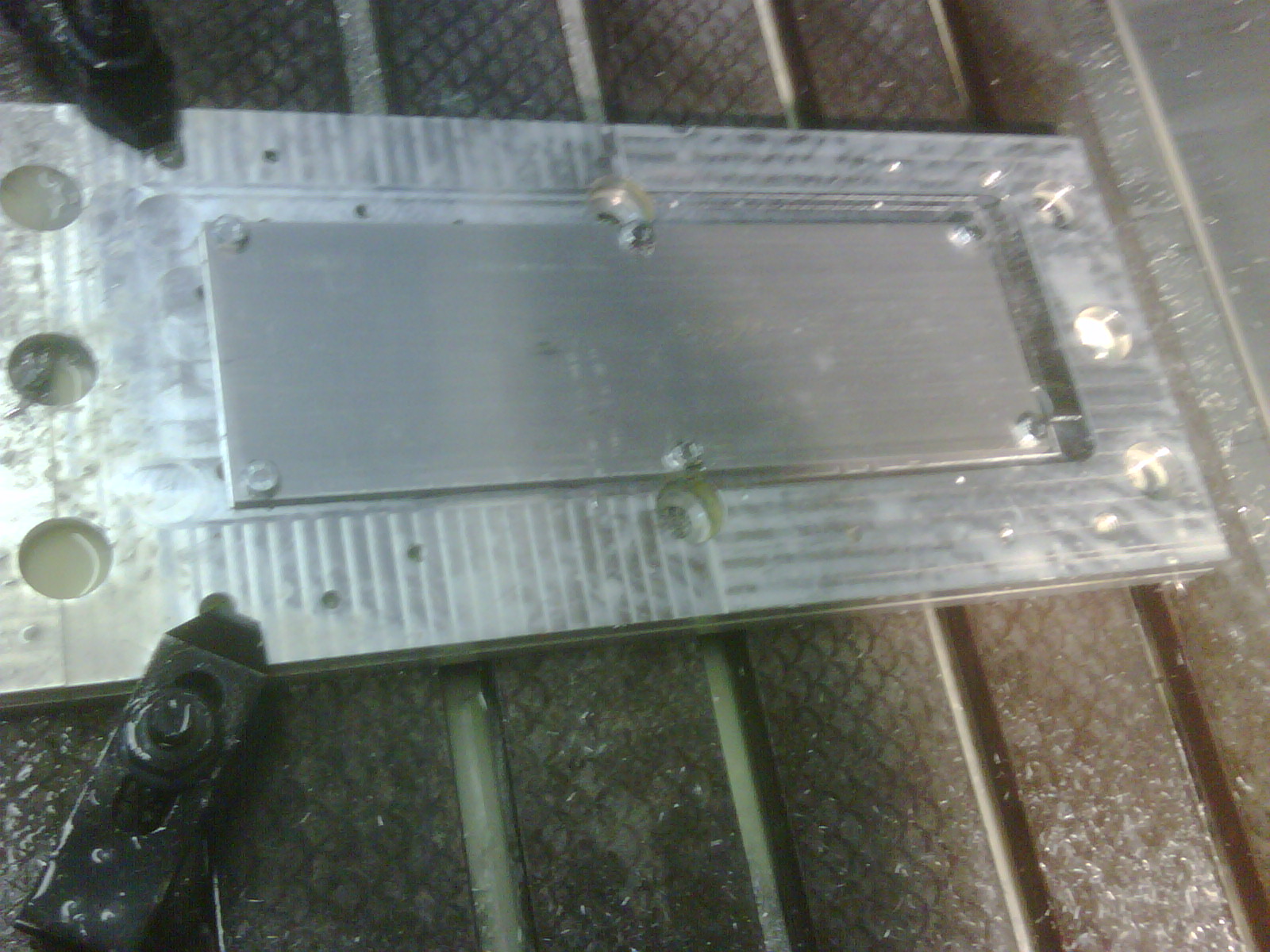
I needed to make some flat manifold plates for a customer. These were to be CNC milled out of 1/4 inch aluminum. The first step was to determine how they were to be held in my CNC. The problem here is that the parts need to be profiled inside and out, making vise clamping or the like unfeasible. As the parts do have bolt holes in them, I could have held the material down with clamps and then pre-drilled the bolt hole pattern. Then, I would have tapped holes in the fixture plate (which is just a scrap of aluminum I use for these sorts of projects) and bolted the material down. The only potential problem with that is that the bolts could mark the surface on the parts. I decided instead to put bolts into the material that would be cut away during machining.
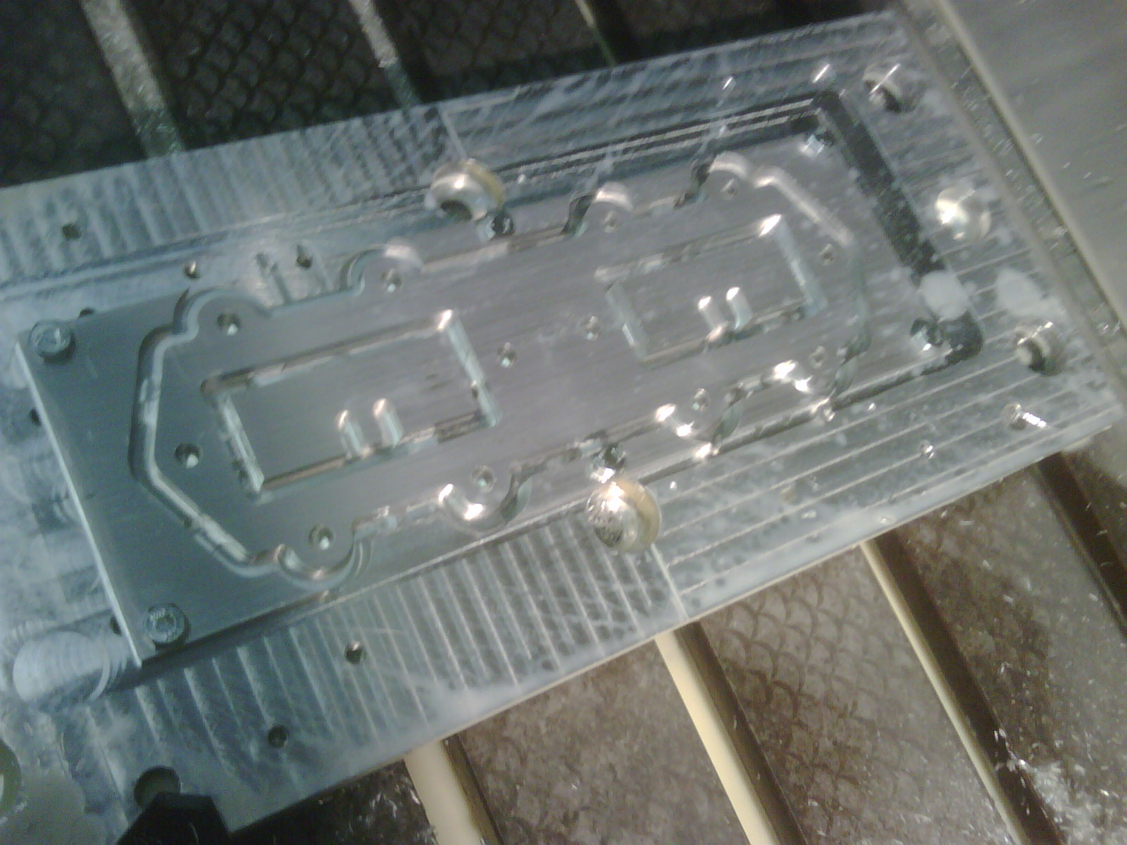
By not using the bolt holes in the part, when I finished machining this job the part would not be held by anything. That is a great way to throw it through a safety shield and bust an endmill. Not good. I used a technique where the part would be held with thin tabs at intervals around the part. My CAM system has the ability to put those in automatically, but if you are manually programming or editing g-code, all you would need to do is pick a spot on the final depth and have the cutter jump up. In this case, I used .025 as a tab thickness, and half inch wide.
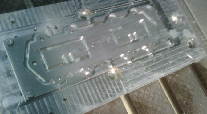
MILLED WITH TABS REMAINING
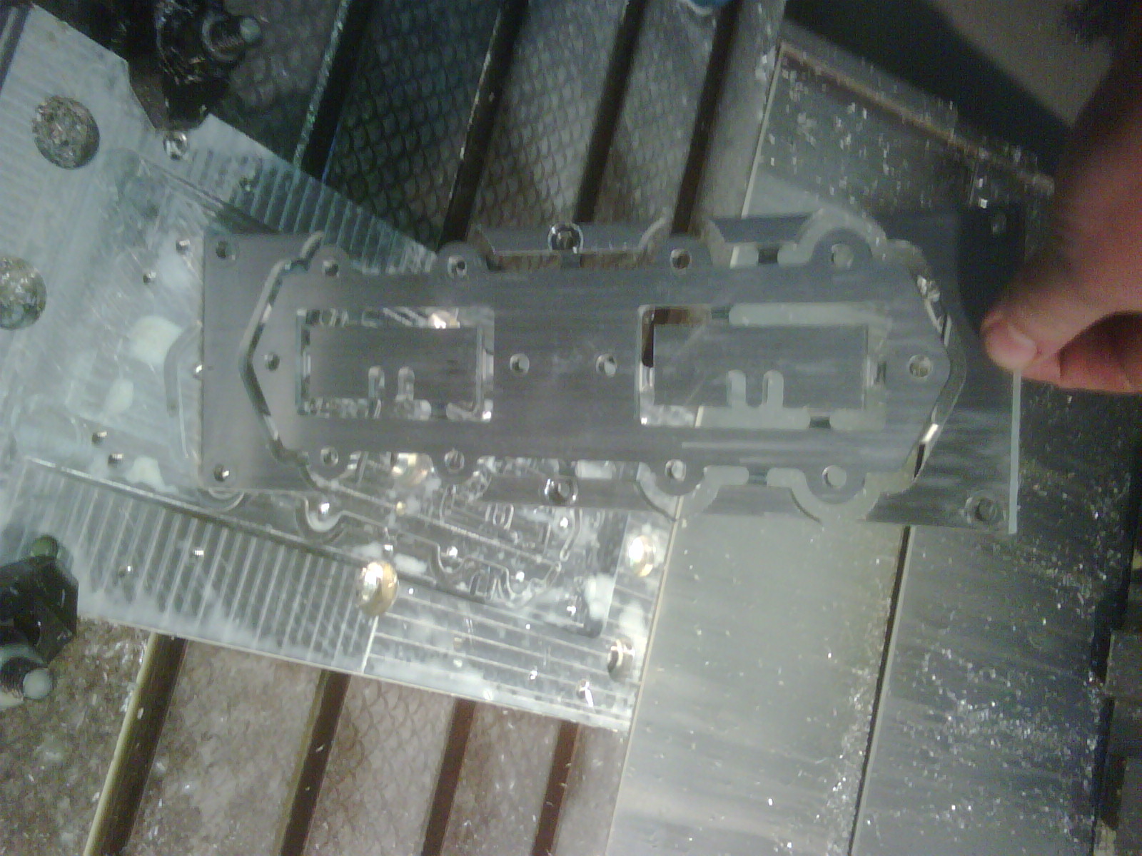
Notice that the part stays together with the remainder material even after I unbolt it.
You have to be careful when choosing your tabs; if they are too thin, they will break during machining and the part will move, possibly wrecking it or damaging something else. If they are too thick, it will be difficult to remove the part from the stock. It should be noted also that the endmill moving up the side of the part like that WILL leave a witness mark. In this case, it really didn’t matter. This could have been minimized by having the CNC make more passes around the part, and then a finish pass that only skimmed over the tabs. The machinist has to decide what’s important for those considerations; I chose speed.
This is an old post, originally written for the shop I opened in Minnesota.
Note: This is not meant to be a comprehensive guide to fixing your mill. It is a recounting of my experiences fixing MY mill. Follow these instructions ONLY if you are qualified to disassemble and service your mill!
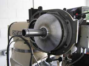
In an effort to save cash while starting this shop, I bought a used Chevalier knee mill, with a Prototrak M3 control.It has been a pretty good mill. It fits what I wanted to start: CNC control, good for manual work too, and cheap. The nice Russian guy I bought it from said, “Oh, it need new belt!” to explain the noise. He was partly right.
There isn’t a whole lot of information on the web about Chevalier mills (there’s decent info about Bridgeport 2J head mills, which this is more or less a copy of, but it’s not exactly the same). They are still in business, though, so I called up the office in California. Since the mill is so old (2002), they didn’t have a manual. For $65, they’d photocopy the one they had. Fine. They did, and did not properly orient the pages, so you have to hunt around. Also, the manual is pretty vague about some things. I thought I’d try to fill in some of the gaps.
The first thing you have to do is tilt the head 90 degrees to one side. I went to the left, because the CNC control is on the right. Turn the mill on, and wind it down to the lowest speed. Turn the mill off and unplug it.
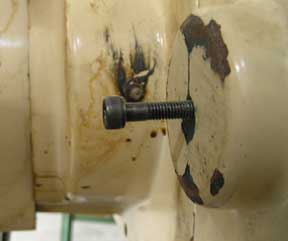
Underneath the motor is a plate, held on with 3-6mm SHCS. Remove those. Then, take one of the screws and thread it into the hole in the center of the plate, as shown.
There is a bearing that fits into the boss in the plate. Most instructions assume the bearing will stay with the plate. In my experience, it won’t! This is a bit of a problem, but not that big of a deal.
The next step is supposed to be “thread some 6mm screws into the holes in the motor pulley, to compress the main spring.” Compressing this spring will make it easier to remove the main drive belt (since this spring is what puts pressure on that belt). If the bearing didn’t come off, you won’t be able to compress the spring. You can work around this, like I did.
Run the speed changer all the way up. Remove the screw that holds the power cable to the side of the mill head, and unscrew the main switch from the housing (you DID unhook the power like I told you, right?). Let those hang loose. Now, pull the two bolts that hold the motor to the head casting. On a Bridgeport, there are 3 bolts, but oh well. You will need to support the motor as you do this, as it is VERY HEAVY.
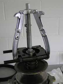
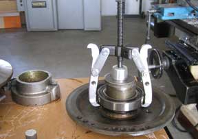
The belt should be somewhat loose, since you ran the speed up, which released the front pulley some. It would be looser if you were able to compress the spring, like I wasn’t able to. Remove the motor, and set on workbench. If the bearing is still attached, remove it with a 3 jaw puller and a bearing splitter.
REMOVING THE LOWER MOTOR BEARING
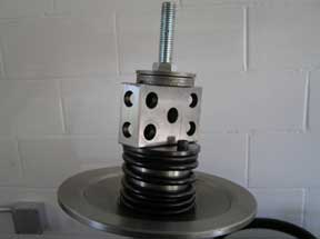
Now, you will be able to compress the spring. Put 2 longer 6mm bolts into the holes in the lower pulley, as shown. Tighten the bolts to hold the spring in place.
6MM BOLTS TO HOLD SPRING
Once you have the spring compressed, remove the C-clip that holds the spring retention plate in place. You should then be able to remove the lower pulley from the motor shaft. DO NOT REMOVE THE BOLTS HOLDING IN THE SPRING.
In the bore of the pulley, there is supposed to be a Teflon bushing. Most likely it is gone, which is one of the reasons the mill is noisy. I purchased new pulley plates for mine (directly from Chevalier’s office in Sante Fe Springs, CA). I also found that the brass key that is supposed to keep the pulley aligned with the shaft had come loose, and jammed between the upper and lower plates, keeping the spring from compressing the belt. This was the source of my slippage, not necessarily a worn belt. Still, since I had it all apart, I put in the new Mitsubishi belt I had purchased.
NEW TEFLON BUSHING AND BRASS KEY
To remove the spring from the old pulley, I put a piece of 1/2-13 threaded rod through the pulley, with some honkin’ big washers on one end, and a 1-2-3 block on the other (to allow access to the bolts). Tighten the threaded rod assembly down onto the pulley, and then you can safely remove the spring compression bolts. Then, slowly release the threaded rod, and the spring will be safely de-compressed.
USING THREADED ROD TO COMPRESS SPRING
Once you have the spring off of the old pulley, you can reverse those steps to put the spring onto the new pulley. Finish with the bolts threaded into the pulley, so you can reassemble once you get the rest of the mill fixed.
Next, remove the main housing. First, remove the bearing assembly at the top of the draw bar (remove the drawbar first). There are three bolts that hold this bearing and on. Unscrew these, and then screw them into the adjacent screw holes, which will jack the plate and bearing out. Or, if your mill is like mine, you will find that the factory neglected to drill and tap these holes! I used a couple of small pry bars to slowly jack the plate up. Once I had it off, I drilled and tapped the holes, so the next time I have to take this thing apart, it won’t be a problem.
Inside the housing, you will see two small bolts (3mm I believe) that attach the variable speed pulley to the plate that pushes it up and down when you crank the handle. Remove those. Next, remove the lower two bolts on the variable speed assembly on the front of the mill (below the speed indicator dial). Then, remove the six bolts on the underside of the housing, that hold the housing on. Please note, the housing is a heavy casting, so use care in removing these bolts!
LOWER VARIABLE SPEED PLATE
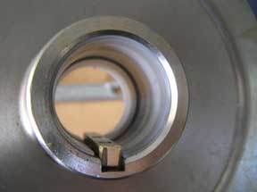
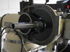
With the housing and the upper pulley removed, this is what the mill looks like. To replace the timing belt, you do NOT need to remove the lower pulley. The bolts are accessible with the pulley in place. Take this assembly off, and replace the belt. After you clean everything well, replace the assembly. You will need to jiggle the belt around to get it on the gears, and keep it from getting pinched.
To replace the moving plate from the variable drive, you will need to remove the little housing that attaches it to the drive plate, and then remove the bearing. The plate pops up fairly easily with a couple of wedges or pry bars, and then use a 3-jaw puller to remove the bearing.
REMOVING THE VARIABLE SPEED BEARING
If all the bearing are fine, you can reuse them. Check them for a gritty feeling. Bearings really aren’t expensive, so as long as you have it apart, you may as well replace them, however. To press them back into place, I used my threaded rod again, and a piece of heavy tubing that would fit over the spindle. This worked as a good low-budget press.
MITSUBISHI TIMING BELT INSTALLED
Once you have the timing belt in place, it is really just a matter of reversing the steps. My only re-assembly tip is to not remove the bolts that compress the motor spring until you have the motor back in place. This makes it easy to get the belt around the pulleys.
EDIT: I closed my shop and sold this mill some time ago. I mostly posted this in case anyone might want to do the same repair. It wasn’t that hard, but I don’t recommend just anyone undertake this. Again, only attempt this sort of repair if you are qualified.